Step 11. Installing the Heatsink Support Assembly
Photo 16 shows the parts of the heatsink support assembly. The heatsink support base installs on the motherboard and serves to provide a stable base for the processor module heatsink. The legs of the heatsink support base are different sizes. You can only install the heatsink support base oriented in one direction.
The heatsink support clip attaches the heatsink to the heatsink support base after the processor module has been installed in the motherboard. This process is described beginning with Step 27.
The two pins that are circled in the picture are inserted through the bottom of the motherboard into the legs of the heatsink support base after it has been positioned on the motherboard as shown in Photo 17.
The mounting holes for the heatsink support base are roughly
indicated by the two arrows in Photo 16. Position the heatsink support base
in the mounting holes with the larger leg of the base in the larger hole of
the motherboard. If you have trouble identifying the larger hole, turn the motherboard
over and position the heatsink support base on the backside of the motherboard
to how the holes match up.
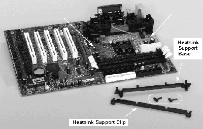
Photo 16. The Heatsink Support Assembly
After positioning the heatsink support base on the top of the
motherboard, turn the motherboard over and insert the two retaining pins through
the bottoms of the heatsink support base legs as shown in Photo 17.
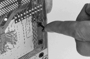
Photo 17. Bottom of Motherboard,
Installing the Heatsink Support
Photo 18 shows the heatsink support base properly installed on a motherboard. Leave the heatsink support clip off the support base until later in this procedure.
Go to Step 13.
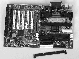
Photo 18. Top of Motherboard, Installing
the Heatsink Support
top
Step 12. Remove the Heatsink Support Clip
The heatsink support clip is shown in Photo 16. Remove the clip from your
already installed heatsink support by squeezing the small tabs on the end of
the clip and sliding the clip off the base as shown in Photo 19.
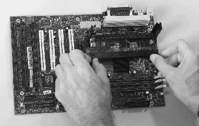
Photo 19. Remove the Heatsink Support Clip
top
Step 13. Verify Motherboard Jumper Settings
Most AMD Athlon processor motherboards do not have jumper settings for processor speed or voltages. However, there may be jumper settings for other features on your motherboard as shown in Photo 20.
Consult the reference manual for your motherboard to determine any jumper
or switch settings that may be required.
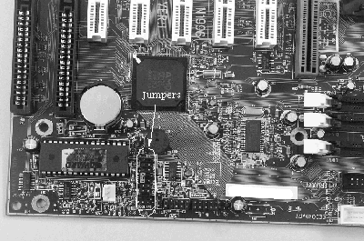
Photo 20. Verify Motherboard Jumper Settings
top
Step 14. Prepare the Punchout Access Ports
Your motherboard has cable connectors for the keyboard, mouse, serial, and parallel ports, etc. These connectors are accessed through punchout holes in the case.
Place the motherboard near the punchout access ports in the case and determine which punchouts you want to remove as shown in Photo 21.
Photo 22 shows a typical punchout being removed with a pair of needlenose
pliars.
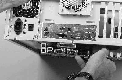
Photo 21. Locate the Punchout Access Ports
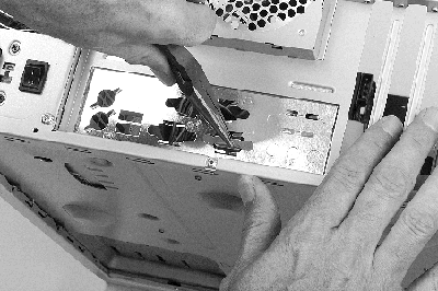
Photo 22. Removing an Access Port
top
Step 15. Preparing to Install the Motherboard
in the Case
The motherboard will be installed on standoffs in the base of the case. Photo 23 shows standoffs in a typical case.
Photo 23 also shows a location where an extra standoff can be installed. Extra standoffs may be needed to provide support in areas of high potential mechanical stress on your motherboard, like the area where circuit cards are inserted. Photo 26 shows an extra standoff installed in a case.
Extra standoffs are included with the hardware that comes with your case. They are usually brass or brass-like and they have male threads on one end and female threads on the other end. The male threads secure the extra standoff to the case. The female threads hold a screw that is used to secure the motherboard to the extra standoff.
Extra standoffs can be secured to the case by applying Locktite to the screw threads before installing the extra standoff as shown in Photo 24.
Photo 25 shows the extra standoff with Locktite on it being installed in the
case. The Locktite will secure the extra standoff in the case so it won't back
out if you ever need to remove the motherboard.
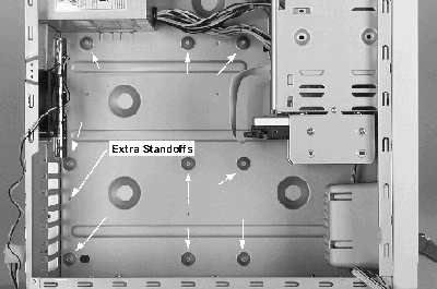
Photo 23. Standoff Bulbs in the Case
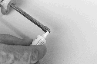
Photo24. Placing Locktite on the Male Threads of the Extra Standoff
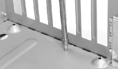
Photo 25. Installing the Extra Standoff
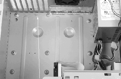
Photo 26. An Extra Standoff That has been Installed
top
|


