Step 6. Remove Blocking Plates
Your case may have snap out plates blocking the front access to the floppy
disk drive and CD-ROM drive. Remove these plates if they exist.
(Many cases do not have blocking plates installed for the three
basic disk drives.) You can usually use a screwdriver to snap
the blocking plates out.
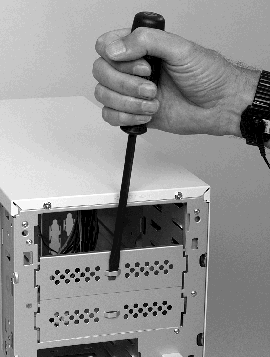
Photo 8. Remove Blocking Plates
top
Step 7. Get Familiar with Your Drive Cable Connectors
In Step 8, you will install the drives in the case. Before you
do that, you should become familiar with the cables that are used
with the various drives.
Photo 9, "Floppy Drive Connector," shows the logic cable that
is plugged into the floppy disk drive. Notice that the cable has
a dark stripe on the right side. This stripe is usually red and
it mates with the pin 1 side of the cable connector on the floppy
disk drive.
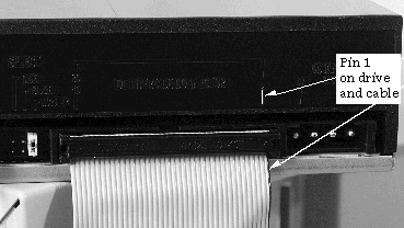
Photo 9. Pin 1 on Floppy Drive Connector
Photo 10, "Keyed and Unkeyed Cables," shows two cables that
are the same except the bottom one has keys and the top one doesn't.
You may get either type with your motherboard. If you have the
keyed type of cables, it will be very apparent where the cable
can be plugged in. If you have the unkeyed type of cable, you
must depend on the pin 1 colored stripe to show you how to match
the cable to the cable connector.
Notice that in Photo 10, "Keyed and Unkeyed Cables," both cables
have a red marking for the pin 1 side. The cable on the bottom
has a dashed stripe for pin 1.
Photo 11, "UDMA-66 versus Regular IDE Cable," shows a UDMA/66
(ATA-66) cable versus a regular IDE cable. The UDMA/66 cable is
on top and it has much thinner wires to allow 80 wires in the
cable. The cable on the bottom has only 40 wires that are obviously
thicker.
Photo 12, "40-Pin Connector on the Hard Disk Drive," shows a hard
disk drive connector that uses a 40-pin connector. Hard disk drive
cables are connected to the drive with pin 1 (the red stripe)
towards the power connector. The arrow in Photo 12 shows the location
of pin 1 on the connector.
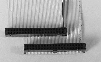
Photo 10. Keyed and Unkeyed Cables
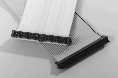
Photo 11. UDMA-66 versus Regular IDE Cable
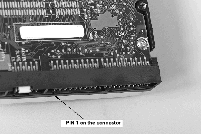
Photo 12 40-Pin Connector on the Hard Disk
Drive
top
Step 8. Install the Drives
Install the floppy, CD-ROM, and hard disk drives in the appropriate
locations in the case as shown in Photo 13, "The Drives Installed
in the Case."
Install the appropriate flat data cables on the drives before
you seat the drives permanently. It can be difficult to install
these cables after the motherboard and other components are installed
in the case.
If necessary, secure the drives in the case with the screws that
were supplied with the case.
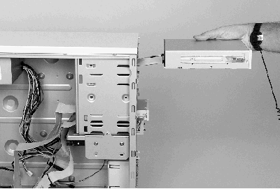
Photo 13. The Drives Installed in the Case
top
Step 9. Motherboard, Case, and Processor
Module
Remove the motherboard and AMD Athlon processor module from their respective boxes. Set aside the CD-ROM or floppy disk that comes with the motherboard to be used later when you are installing drivers for the system.
The AMD Athlon Processor-in-a-Box product comes with a Certificate of Authenticity/Installation
Guide and a plastic bag with a heatsink support in it. Set the Certificate of
Authenticity/Installation Guide aside and keep the plastic bag in your workspace.
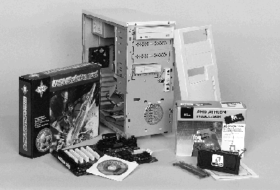
Photo 14. Motherboard, Case, and Processor
Module
top
Step 10. Motherboards With and Without
a Heatsink Support
Photo 15 shows two motherboards that are very similar except
for the heatsink support that is installed on the motherboard
on the left.
Notice that the motherboard on the right has processor module
guides that can be folded down. These guides will need to be folded
up when you install the processor module in the guides.
If your motherboard has a heatsink support installed on it, go
to Step 12.
If your motherboard does not have a heatsink support installed,
go to Step 11.
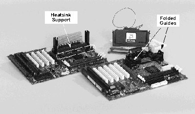
Photo 15. Motherboards With and Without a Heatsink Support
top
|


