Processor Installation
There are retention latches on the top of the processor module. Normally, the processor is shipped with the retention latches disengaged. If they are disengaged, they will feel a little loose.
Before the processor installation, you must push the retention
latches in firmly until they click. The latches are located at the very top
corners of the processor as shown in Photo 38.
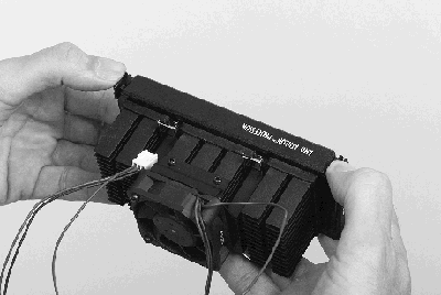
Photo 38. Press the Retention
Latches In
top
Step 27. Place the Heatsink Clip in the
Heatsink Fins
Install the heatsink support clip between the first and second rows of fins at the bottom of the heatsink as shown in Photo 39. The openings of the locking slots on the heatsink support clip should be facing up.
The heatsink support clip is symmetrical--there is no designated top or bottom--you
can install it either way. However, there is a front and back. The locking slots
must face up.
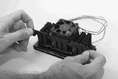
Photo 39. Place the Heatsink Clip in the Fins
top
Step 28. Install the Fan Power Cable
Before you install the processor, install the power connector for the processor fan. Check your motherboard reference manual for exact details.
On most motherboards, the power connector is located between the processor connector socket and the AGP card slot. The connector is keyed.
Install the connector carefully on the power pins on the motherboard. Make
sure it is firmly seated.
Warning: There is a thermal sensor ribbon on the motherboard at the
point where the processor module is inserted. In the lower right portion of
Photo 40, there is a circle with an arrow pointing to it. The circle is in the
vicinity of the ribbon sensor.
Exercise caution when inserting the processor module. Do not crease or break
the thermal sensor ribbon. And be certain the ribbon is not caught under the
processor module and blocking the card edge.
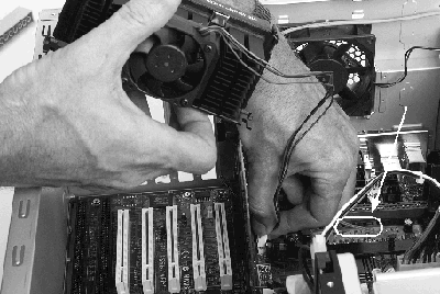
Photo 40. Install the Fan Power Cable
top
Step 29. Slide the Processor Module into
the Guides
The processor module guides may be folded down. Photo 15 shows a motherboard with the processor module guides folded down. If the processor module guides are folded down, fold them up.
The heatsink support clip must be pushed fully into the fins or the clip will jam and you will not be able to seat the processor module.
Slide the processor module squarely into the processor module guides and then
squarely into the processor socket. Make sure the processor module is fully
seated in the socket.
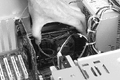
Photo 41. Slide the Module In
top
Step 30. Firmly Seat the Processor Module
Push the processor down firmly to make sure the processor is fully seated.
Visually inspect the processor module to verify that it is full inserted.
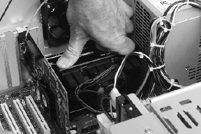
Photo 42. Firmly Seat the Processor Module
top
|


